Kanzen amp III
Introduction
Current positive feedback is employed because I study bass reflex
system
these days. As you look at this circuit this is a kind of voltage
feedback
detecting output current. Amount of feedback is variable but I
don't understand
this circuit well which is similar to inverted amplifier. It
seems to be difficult
to innovate this amp for I don't know about phase compensation.
This circuit is named "Bridged feedback" which I've
never seen before.
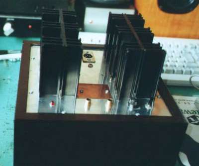
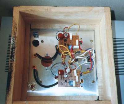
Making of Kanzen amp III
This is the looks of Kanzen amp III. It looks rather dull but
practical. Large
sized circuit board is prepared because it makes easier to add
the circuit
of positive feed back.
At final stage Toshiba C3281,A1302 is employed, because they are
easy
to buy and its cost is reasonable. Mark Levinson No.383L employs
these
devices too. At first stage Toshiba K170 is employed. This has
higher gm
than K117, therefore open loop gain becomes larger. Capacitors
are Okaya
Vx this time.
Hfe of PNP transistor is necessary to be measured. By this
measurement
the value of first stage current is decided. Measurement of NPN
transistor
is not necessary.
Idss of K170
Idss of K170 was measured. 25 pieces were measured and 8 pieces
were
selected.
| L ch |
1 |
4.06mA |
for first stage |
| |
2 |
4.07 |
for first stage |
| |
3 |
4.08 |
for fixed current |
| |
4 |
about4 |
for bias of NPN |
| R ch |
1 |
5.06 |
for first stage |
| |
2 |
5.07 |
for first stage |
| |
3 |
4.76 |
for fixed current |
| |
4 |
about4 |
for bias of NPN |
By this measurement idle current
of the final stage will be
Lch (4.08/2)*172=350 mA
Rch (4.76/2)*151=359 mA
Lch board was assembled successfully.
There is no oscillation. Music is played
clearly. Idle current is 350mA. Current positive feedback is not
applied yet.
For a while I have to confirm the sound of Toshiba.
Both channels were completed. The sound is warmer tha NEC. When I
listened
to Steve Reich'Us CD, I found this sound was that of familiar
Kanzen amp. The
anxiety was relieved. idle current was settled to the planned
value.
Pwer transistors whch are now available will e Tosiba's
orSanken's. Sanken's
transtor have highher ft. They may have diferent sound charactor.
Ouput impednce of Kanzen amp is approximatey 8 ohm, so iis a mild
crrent output amplifer. It never breaks speakers by overdrive at
fo.
It has milder magnetic damping than voltage output amplifier, so
they
have different transient characteristics.
Final circuit
At VR=50K, Z=7.0 ohm and at VR=0 ohm, no sound is heard. This
time VR is
tuned for Z to be 5.7 ohm. Without current positive feedback
Z=8.28 ohm.
Minus impedance is impossible at Kanzen amp, so this project is
finished.
July 30 , 2000
index